EMF Exposure

I'm just curious, but how and does the website EMFields Solutions (_http://www.emfields-solutions.com/howto/what-to-do-about-dirty-electricity.asp) sell an almost identical DE meter to that of Greenwave's? :huh:

Are they sourcing from the same manufacturer somewhere in the People's Republic of China?
 
beetlemaniac said:
I'm just curious, but how and does the website EMFields Solutions (_http://www.emfields-solutions.com/howto/what-to-do-about-dirty-electricity.asp) sell an almost identical DE meter to that of Greenwave's? :huh:

Are they sourcing from the same manufacturer somewhere in the People's Republic of China?

No idea, but it does look identical.

Interesting - it also says:

The deTekta meter measures the amount of Dirty Electricity (DE) that is on your house wiring. It shows the readings in millivolts (mV) on a screen and also presents it as an audio signal. It is available to buy or to hire (Hires come with the use of 2 filters, which can be purchased at a discount whilst you have the meter on hire).
 
Something interesting about the TriField 100XE - it comes in three different versions which weight the EM frequencies detected. There are 50Hz, 60Hz and flat frequency models. This from their website:

_http://www.trifield.com/content/trifield-broadband-meter/ said:
Standard Version Frequency Weighting:
*Sensitivity is proportional to frequency from 40 Hz to 500 Hz; flat from 500 Hz to 2000 Hz
*Sensitivity is inversely proportional to frequency from 2K Hz to 100K Hz
Flat Frequency Version: +/- 20% from 50 Hz to 500 Hz; inverse frequency above 500 Hz

I tend to agree with your previous post, LQB, on the idea that the AC powerline frequencies are not as harmful as the high frequencies that have progressively invaded our homes thanks to all the badly designed new-fangled appliances flooding the market. Thus, I would think that the flat frequency model would be an ideal choice compared to something (for both mag and elec fields) that gives readings skewed towards grid frequency. Thoughts?
 
I understand that many of you are worrying about EMF effect on biological systems, but what would be the mechanism for interraction of RF onto biological systems except than heating due to Joule effect?

If any effect of RF field were to exist onto biological system, we would see some "peaks" of absorbtion using a spectrum analyser. None are observed.

There are protein structures called α-helix that exhibit low frequency Raman resonnance at 25cm-1 but I doubt it translate into "practical" RF significant absorption band.

Any idea?

I possess equipments capable to measure absorption of RF energy from LF to 1GHz. Anyone want me to do some tests?
 
beetlemaniac said:
Something interesting about the TriField 100XE - it comes in three different versions which weight the EM frequencies detected. There are 50Hz, 60Hz and flat frequency models. This from their website:

_http://www.trifield.com/content/trifield-broadband-meter/ said:
Standard Version Frequency Weighting:
*Sensitivity is proportional to frequency from 40 Hz to 500 Hz; flat from 500 Hz to 2000 Hz
*Sensitivity is inversely proportional to frequency from 2K Hz to 100K Hz
Flat Frequency Version: +/- 20% from 50 Hz to 500 Hz; inverse frequency above 500 Hz

I tend to agree with your previous post, LQB, on the idea that the AC powerline frequencies are not as harmful as the high frequencies that have progressively invaded our homes thanks to all the badly designed new-fangled appliances flooding the market. Thus, I would think that the flat frequency model would be an ideal choice compared to something (for both mag and elec fields) that gives readings skewed towards grid frequency. Thoughts?

Mag field meters are not good for measuring the high frequency grid noise - the fundamental and low frequency harmonics are orders of magnitude greater than the high freq noise components that you want to measure. Electric field noise begins to penetrate flesh at about 2.5KHz - lower frequencies ride on the skin (via elec capacitive coupling). So the general methodology is to use the grid meters to measure the grid noise, filters to reduce the noise, and 50/60Hz elec/mag meters to evaluate/minimize your exposure in the home (especially identifying/fixing home wiring errors).
 
Astrocyte said:
I understand that many of you are worrying about EMF effect on biological systems, but what would be the mechanism for interraction of RF onto biological systems except than heating due to Joule effect?

If any effect of RF field were to exist onto biological system, we would see some "peaks" of absorbtion using a spectrum analyser. None are observed.

There are protein structures called α-helix that exhibit low frequency Raman resonnance at 25cm-1 but I doubt it translate into "practical" RF significant absorption band.

Any idea?

I possess equipments capable to measure absorption of RF energy from LF to 1GHz. Anyone want me to do some tests?

For EM RF, one of the mechanisms proposed is interference with mitochondrial function and the crucial millivolt potentials that must be maintained for energy production and waste product elimination. A web search will produce many papers on the subject including measurements.

There are also many papers dealing with RF absorption by the body as a function of frequency, geometry, proximity, etc. Look for SAR - specific absorption rate/ratio.
 
Astrocyte said:
I understand that many of you are worrying about EMF effect on biological systems, but what would be the mechanism for interraction of RF onto biological systems except than heating due to Joule effect?

If any effect of RF field were to exist onto biological system, we would see some "peaks" of absorbtion using a spectrum analyser. None are observed.

There are protein structures called α-helix that exhibit low frequency Raman resonnance at 25cm-1 but I doubt it translate into "practical" RF significant absorption band.

Any idea?

I possess equipments capable to measure absorption of RF energy from LF to 1GHz. Anyone want me to do some tests?

From what I've read and what I remember in chemistry- the induced currents can damage cells as you stated- by heating.

There is also a problem with how chemical bonds are created/broken. As that involves exchange of electrons, electrical interference can stop or accelerate processes.
That's the same reason why Flourine, Mercury, Lead can damage us, they can stop processes!
 
Astrocyte said:
I understand that many of you are worrying about EMF effect on biological systems, but what would be the mechanism for interraction of RF onto biological systems except than heating due to Joule effect?

If any effect of RF field were to exist onto biological system, we would see some "peaks" of absorbtion using a spectrum analyser. None are observed.

There are protein structures called α-helix that exhibit low frequency Raman resonnance at 25cm-1 but I doubt it translate into "practical" RF significant absorption band.

Any idea?

I possess equipments capable to measure absorption of RF energy from LF to 1GHz. Anyone want me to do some tests?

We already know that EMF has a harmful effect on many people - that has been established through research. I think engineers tend to miss the whole point when they dismiss it based on a few well-known concepts. Engineers are familiar with the levels of RF that cause obvious damage, but anything less than that is a whole different science.

Heating is not necessary for RF to cause damage. Furthermore, it seems modulated RF is more dangerous than steady tones. So I suspect a some of the problem could be demodulation at the boundaries of different substances, altering charge gradients and causing currents through tissue.

I don't know if measuring SAR would be very useful, because it doesn't distinguish between benign absorbtion and harmful absorbtion. Probably, only a small part of the harm is due to heat, and only a fraction of the absorbtion causes the harmful effects.

Maybe a useful measurement would be to pass RF through some living tissue, and try to detect demodulation occurring in the tissue. Since we're talking about things that happen on the molecular scale, there may not be a detectable signal, but who knows.
 
Hi LQB, it was mentioned in the 16 April 2016 session that Greenwave's filters are line-to-ground filters. Could this mean that they use Y class capacitors; or are the filters built like this? I'm working on building my own filters thus I'm curious on how best to build them.
 
beetlemaniac said:
Hi LQB, it was mentioned in the 16 April 2016 session that Greenwave's filters are line-to-ground filters. Could this mean that they use Y class capacitors; or are the filters built like this? I'm working on building my own filters thus I'm curious on how best to build them.

I have no idea what they actually do to implement their filters. Years ago I talked with the partner/developers at length, but not about their filter design.
 
Line to ground would be the best way to neutralize fields that affect us- because only appliances feel the noise between phases or phase to neutral.

However, I'm a bit disappointed in those schematics. From what it looks like, you have 180 uF Line to ground and 180 uF Neutral to ground. The resistor does nothing here, it's not an inductor, this is not a tuned filter. The resistors are used to discharge the capacitors when you unplug the filter.

Capacitors can help to remove spikes and smooth out the sine wave, but pretty much most electronic power supplies do the same thing because they aim for high power factor (which requires capacitors in order to balance out inductance).

Sure, with a meter you might find noise reduction at THIS outlet, but overall, could someone try this experiment:

1)Measure noise pre filter install at that outlet, circuit. Measure noise also at some other outlet in a different circuit.

2)Install filter, measure noise at that outlet, circuit. Measure noise at the same other outlet you used in step 1.

My feeling is that since the spikes are relatively tiny to the normal wave. Since they are so small, the filtering is localized, like we see at work with VFD capacitor banks. They can clean noise at the VFD but at the main we can have harmonics that seem to "reflect" back. I don't know enough about the way these waves reflect, but I think the problem is that like an antenna, they are dependent on the length of each wire and attached loads. Our house wiring may be static, but the appliances on the wiring change the inductance/capacitance all over.

I don't see how these filters do much more than give good localized tests.
 
Divide By Zero said:
Line to ground would be the best way to neutralize fields that affect us- because only appliances feel the noise between phases or phase to neutral.

However, I'm a bit disappointed in those schematics. From what it looks like, you have 180 uF Line to ground and 180 uF Neutral to ground. The resistor does nothing here, it's not an inductor, this is not a tuned filter. The resistors are used to discharge the capacitors when you unplug the filter.

Yes, this is my understanding as well. I think the filter is meant to function as a simple low-pass filter.

Capacitors can help to remove spikes and smooth out the sine wave, but pretty much most electronic power supplies do the same thing because they aim for high power factor (which requires capacitors in order to balance out inductance).

Is there a connection between the power factor correction and EMI suppression? Is it only a coincidence that capacitors added to a circuit seem to help with both of these things? I know, this does sound like a stupid question -- I did study electrical engineering but I just could not grasp the concepts very well. :cry:

Sure, with a meter you might find noise reduction at THIS outlet, but overall, could someone try this experiment:

1)Measure noise pre filter install at that outlet, circuit. Measure noise also at some other outlet in a different circuit.

2)Install filter, measure noise at that outlet, circuit. Measure noise at the same other outlet you used in step 1.

Sure, I can try doing this once I get my measuring equipment from Greenwave and build a prototype filter. My filter is going to be pretty simple as a first try -- even simpler than that in the schematic. It'll be an X2 capacitor and resistor in parallel to the line-neutral, with a fuse. I would appreciate your suggestions for improvement if you have any. :)


My feeling is that since the spikes are relatively tiny to the normal wave. Since they are so small, the filtering is localized, like we see at work with VFD capacitor banks. They can clean noise at the VFD but at the main we can have harmonics that seem to "reflect" back. I don't know enough about the way these waves reflect, but I think the problem is that like an antenna, they are dependent on the length of each wire and attached loads. Our house wiring may be static, but the appliances on the wiring change the inductance/capacitance all over.

I don't see how these filters do much more than give good localized tests.

Yes, the effect of the filters would be localised, from what I have read. However, the benefits to human health from the suppression of EMI in a circuit, in a bedroom for example, could be significant enough to warrant using them. The book "Dirty Electricity" by Samuel Milham outlines his studies and observations at schools in the US. In one of those schools (La Quinta), EMI readings were taken in individual classrooms, then the cancer incidence among teachers was correlated by classroom.

However, the observations Dr. Milham made in Vista del Monte were even more shocking, I'll leave you with the following:

Dirty Electricity said:
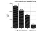
Cancer in Vista del Monte Elementary School in Palm Springs with a Cell Tower on Campus

In February 2010, I received an E-mail from Kim McClinton, a science teacher at Vista del Monte elementary school in Palm Springs, California. She had heard about the La Quinta study and thought her school had the same problem. The school had a reputation for being a “cancer school” in the school district. Since 2005, there has been a cell phone tower located within a few feet of a classroom wing in the school courtyard.

During a visit to the school, I showed Kim how to use the G/ S meter, and she produced a color-coded analysis of G/ S readings by classroom. The entire school had very high dirty electricity readings. Their dirty electricity levels were higher than those at the La Quinta school. The Vista del Monte G/ S readings averaged 1,300 compared to 750 at La Quinta. The cancers (twelve cancers, including six female breast cancers among seventy-five personnel employed at the school since 1990) were over-represented in the wing of the school closest to the cell tower, and the G/ S readings were highest in the classrooms closest to the cell tower base. At the same stage of the investigation, La Quinta school had eleven cancers in 137 teachers. A fourth grade teacher complained that her students were hyperactive and un-teachable. The outlets in her room measured over 5,000 Graham/ Stetzer units. On a Friday afternoon after school, I reduced the measured dirty electricity in the wiring from over 5,000 to less than 50 Graham/ Stetzer units with five plug-in filters. With no change in either the cell tower radiation or the lighting, the teacher reported an immediate dramatic improvement in student behavior in the following week. They were calmer, paid more attention and were teachable all week except for Wednesday when they spent part of the day in the library. Later, the teacher told me that she could change the behavior of the children by removing and reinserting the filters. The change took between 30 and 45 minutes. This young teacher also became the thirteenth cancer case in this small teachers’ cohort. On January 25, 2011, I presented my findings to the Palm Springs Unified School District Board of Education. I sent the Powerpoint of my presentation in advance. I was surprised to learn at the last minute that the board had hired Leeka Kheifets to contest my findings and had provided her with a copy of my presentation. Of course, I had not been given a copy of her presentation. I offered to filter the school at no cost to the district, guaranteeing an improvement in student test scores and attendance. My offer was refused.

One teacher with poorly controlled type 2 diabetes, in spite of insulin injections and oral hypoglycemic medication, had repeated foot infections and a below-the-knee amputation. He retired in 2009, and his blood glucose readings have been normal since then. Magda Havas has shown that dirty electricity raises blood glucose levels and changes insulin requirement in diabetics. The blood glucose connection could be how dirty electricity increases cardiovascular disease incidence. The major mortality and morbidity in diabetics is due to acceleration of cardiovascular diseases. Magda Havas has also shown that radiation from DECT (Digital Enhanced Cordless Telecommunications) phones can cause an instant change in heart rate and rhythm in some exposed individuals. Cell tower transmitters, like most modern electrical equipment, operate on direct current. The electrical current brought to the tower is alternating current which needs to be changed to direct current. This is done by a switching power supply or an inverter. These devices interrupt the AC current and are the likely source of the dirty electricity in the wing of the school closest to the tower. That little device you plug into the wall to charge your cell phone is one of these. They are present in all computers, copy machines, and television sets. This is another serious but unrecognized hazard of cellular telephone technology. People who are concerned about health issues regarding cell towers focus on the RF emissions, but dirty electricity is another unrecognized important exposure. To illustrate just how far dirty electricity effects can extend, after Dave Stetzer filtered a Midwestern school, a dairy farmer a quarter of a mile away noticed that his cows each gave an average of ten pounds more milk per day beginning the day the school was filtered. The cows were responding to dirty electricity being removed from the ground currents.

Milham MD MPH, Samuel (2012-12-06). Dirty Electricity: Electrification and the Diseases of Civilization (pp. 81-82). iUniverse. Kindle Edition.
 

Attachments

  • vistadelmonte.jpg
    vistadelmonte.jpg
    52.4 KB · Views: 79
LQB, in electronics steel enclosures due to their magnetic permeability are used to shield magnetic fields the same way faraday shields are used for electric fields. Is this not effective for panel boxes?
 
Wow, I missed some stuff in this thread.

It's true that the capacitor filters don't help much above a certain frequency. They work best around 500KHz-5MHz as a guess.

Since Romex is essentially a transmission line, the problem with them resonating and carrying reflections has already been solved by engineers and the task remains to apply those insights to house wiring. I can think of some potential ways to correct that issue.

Divide By Zero said:
Line to ground would be the best way to neutralize fields that affect us- because only appliances feel the noise between phases or phase to neutral.

This may be true in countries where the power conductors are balanced. In the US you have L which is 120V and you have N which is 0V, so even after they cancel what remains is a 60V field. Also even with balanced power you can't expect the phases to be matched perfectly, and therefore to cancel perfectly.

Ultimately the noise is generated between the power conductors, and filtering between them will take care of the load surges without forcing the currents to take long routes through the house wiring. If an appliance wants to draw a 100nS surge from L to N, then a L to G capacitor will force the pulse to go through G all the way to the mains box before it bonds with N and can come back to the appliance N. It is important not to confuse common mode and differential mode noise.

However, I'm a bit disappointed in those schematics. From what it looks like, you have 180 uF Line to ground and 180 uF Neutral to ground. The resistor does nothing here, it's not an inductor, this is not a tuned filter. The resistors are used to discharge the capacitors when you unplug the filter.

A filter that works well in all situations is very difficult to design - I've tried very hard. What I need is someone to tell me which forms of EMF need which amounts of filtering, at what frequencies, and at what cost point. Because without that information there is not really a suitable "aim", and the design will never be finished, or if it is finished it will not be very good. You may think the GS filters need an inductor but the question is "for what?".

Capacitors can help to remove spikes and smooth out the sine wave, but pretty much most electronic power supplies do the same thing because they aim for high power factor (which requires capacitors in order to balance out inductance).

I have almost never seen more than 470nF capacitance in a power supply input to a household appliance (except for compressors and other motors). To resonate at 50-60Hz, that would require a 15-20H inductor. If that were used it may double the size of most appliances, and would be extremely heavy. So what do they do instead? They emulate one with a switching circuit. And this is where all the noise gets generated.

Sure, with a meter you might find noise reduction at THIS outlet, but overall, could someone try this experiment:

1)Measure noise pre filter install at that outlet, circuit. Measure noise also at some other outlet in a different circuit.

2)Install filter, measure noise at that outlet, circuit. Measure noise at the same other outlet you used in step 1.

My feeling is that since the spikes are relatively tiny to the normal wave. Since they are so small, the filtering is localized, like we see at work with VFD capacitor banks. They can clean noise at the VFD but at the main we can have harmonics that seem to "reflect" back. I don't know enough about the way these waves reflect, but I think the problem is that like an antenna, they are dependent on the length of each wire and attached loads. Our house wiring may be static, but the appliances on the wiring change the inductance/capacitance all over.

What frequency are the harmonics? If they're under 500KHz, the capacitors may just not be large enough. If above 5MHz, it might be reflections in the cables. Also consider potential "ground loops".

I don't see how these filters do much more than give good localized tests.

The filtering should be placed close to the source, and only then should you consider applying filtering anywhere else. The filter should also work in the frequency range needed, and with the type of EMF that needs to be filtered. So, there are some parameters that need fleshing out and a method needing development (or possibly just discussion)...
 
Back
Top Bottom